The project was to design and fit automatic winding to a 19th century English weight driven tower clock. It was a birdcage type signed "Brockbank and Atkins, 1848".
I discovered after getting it home and reading the seconds bit that the pendulum that came with it had been cut short and that it was designed for a 2 second pendulum (i.e. about 4 metres long). Have you ever seen a 2 second pendulum? The picture shows my second son Titus holding one up.
I was determined to make no permanent alterations to the original mechanism and to use as much of the original mechanism as possible. Also, having learned that it is damaging to a clock train to drive the large wheels by applying power to the small wheels, I wanted to apply the driving power to the weight barrels. An idea explained in the article by John Wilding in "Clocks" invloved not winding the clock but rather applying a permanent maintaining power. But as far as I could discern by making enquiries, that method had never been applied to a striking train, the problem being that it moves so much more quickly than the going train. I decided to adapt the idea to try to drive both trains from their winding squares by mounting a cantilevered motor on each, strong and fast enough to keep up with the striking.
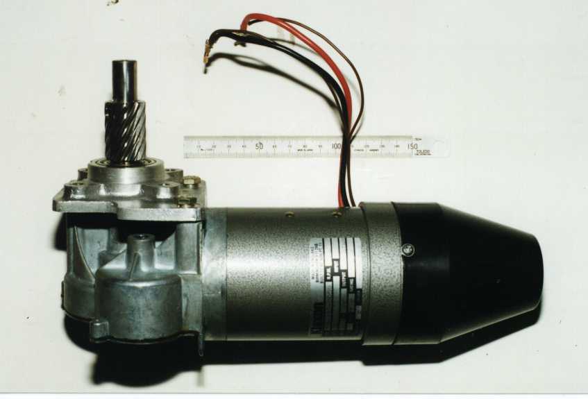
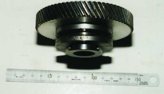
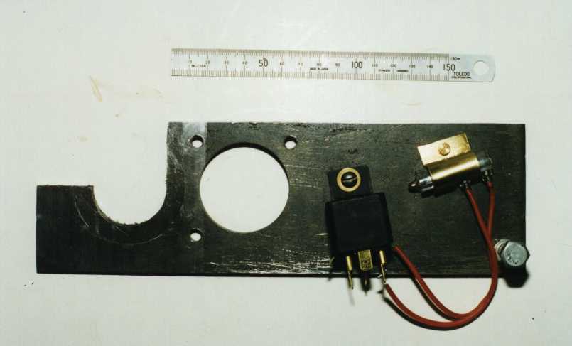
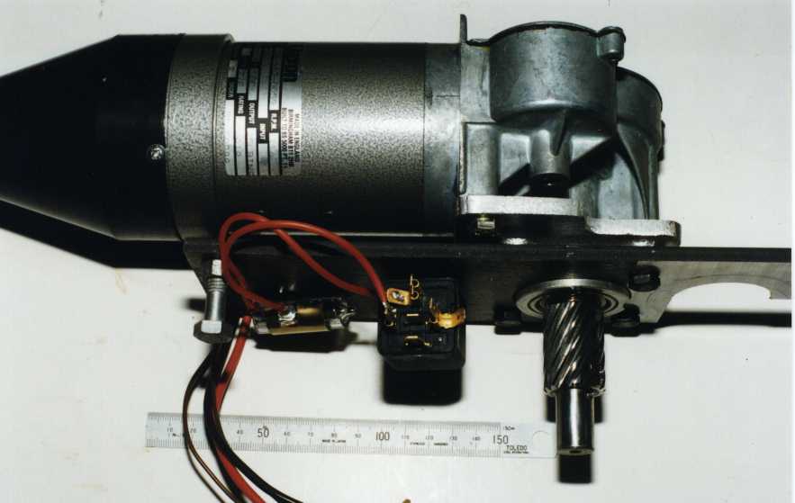
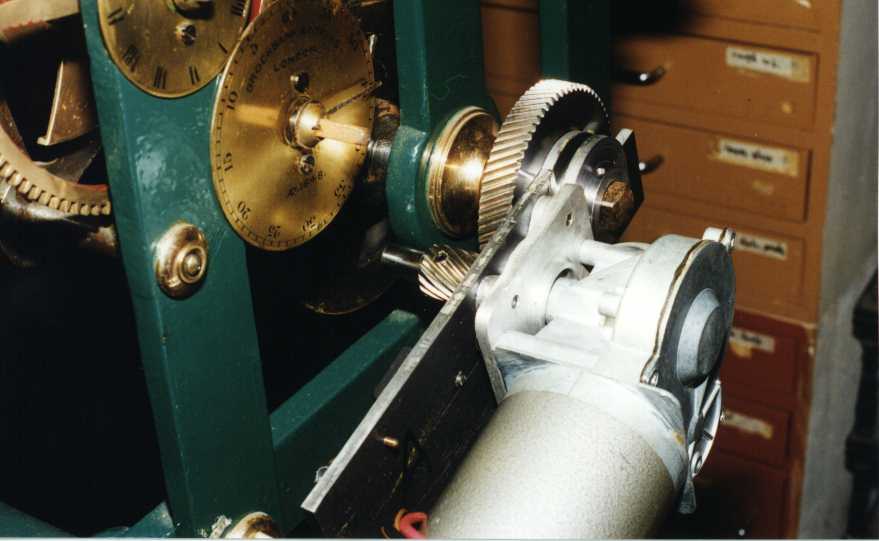
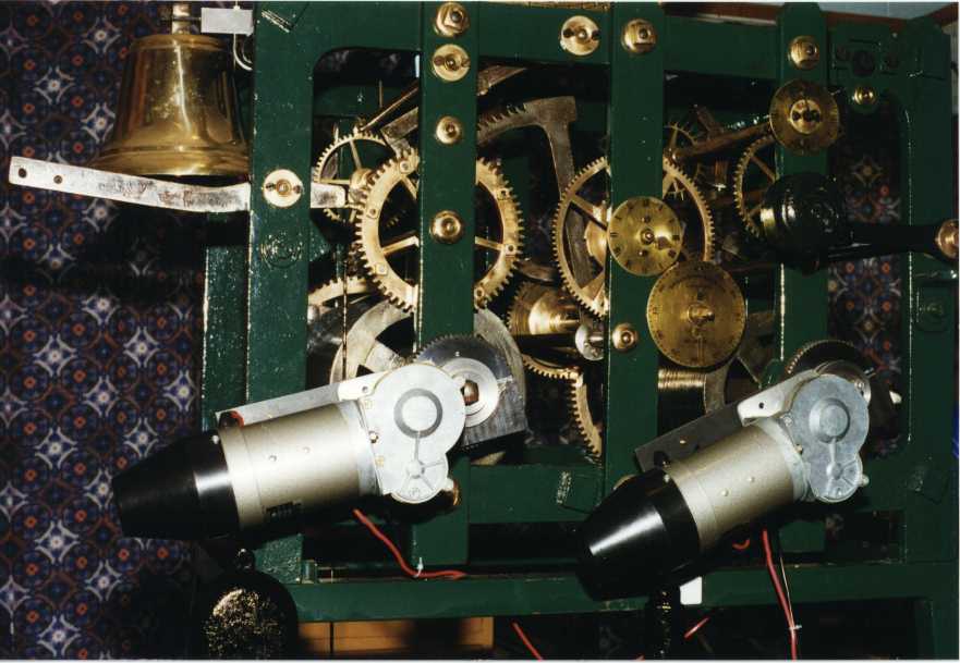
The motor chosen was a 12 volt wheelchair motor with double reduction worm drive. On its shaft I mounted a pinion, and the pinion engaged a wheel mounted on the winding square. The motor and pinion were mounted on a cantilevered mounting plate together with a mercury switch to sense the position of the plate. The photos show the plate assembly from the bottom and the completed assembly in position on the winding square. Of course the same thing had to be done for the winding side, and the photo shows both.
What is the power supply and how much power does it use? I used a 12 v car battery and maintain a floating charge on it with a 0.5 amp charger. The motors ask for up to 25 amps for short bursts maybe once an hour on average.
How much additional weight was needed? There is a bolt projecting from each plate from which variable weight can be hung. I found that 12 lb was sufficient on the strike side, and 2 lb on the time side.
Why the relay? I put an automotive horn relay in so that the current load on the mercury switch would be low. I didn't want to use the mercury switch to switch 20 to 30 amps for fear it would burn out.
Why use spiral cut gears rather than spur? It was simply because they were available at the right price.
You may email me at the address below to let me know what you think or to ask further questions.
David Smith
Auckland, New Zealand